

Whether it was born out of a lifetime fascination with lifelike robots, or out of the simple power fantasy of controlling a mech like so many adrenaline-driven films and movies, I've always wanted to build a robot that could mimic my movements. Something about having a machine follow your commands without needing a controller (known as telecontrol) is just thrilling, immediately making you feel like you're in a movie or sci-fi television show. Luckily, though, you don't need to be a Tony Stark or Asimov to put together a mimic bot. And compared to what it would have taken just a few decades ago (think two stories filled entirely with computers), it's actually fairly easy with some modern tools.
Not to say it's that easy. Mimic Arm ended up being my senior design project at the University of Rochester, along with two other engineers Frank Dinoff and Colin Murphy, and it took almost a year to finish. But if you want to put one together yourself, all it'll take is about $300 (more if you want it to be stronger) and a couple hours of assembly. That's about a $700 dollars cheaper for an arm that ended up working better than anything else we'd could find online.
Here's a video of the final thing in action:
Here's some background as to how we did it (and how you can do it too, if you want.)
The Base Concept:
We started the project with the expectation of creating a robot arm capable of imitating the natural movements of a human arm in real time. We designed the arm with 4 joints, to allow it to hit every possible human arm position minus the motions of the wrist, and rigged it to a Kinect camera to track the operating user. When somebody stepped in front of the camera, the system would track to see where their right arm was, port it into our software program, and then command the robot arm to imitate their real arm as they moved it around:

Similar projects had been done independently a couple times before by other enthusiastic makers online, as well as by some very large and well funded research groups, but almost all of them suffered serious flaws: most of the arms we could find were very slow, they had to use bulky exoskeletons mounted on the human operating them, and they just didn't look very natural. Even the big expensive ones suffered from serious latency issues, lagging far behind the motions of their human operator, and the little ones were jagged and erratic in their motion.
Having personally worked with motion tracking cameras and servos before, it seemed possible that these existing arms were suffering from excessive overhead due to software and constraints they really didn't need for humanlike motion. By stripping out unnecessary features that are not required for telecontrol, we figured we could speed up the system substantially.
With that in mind, we established three goals for the arm that would dictate our design choices.
- Human degrees of freedom
- Camera based tracking
- Superior power and speed
1) Human Degrees of Freedom
The biggest difference between mimic arm and the vast majority of robotic arms that exist today is actually how the mathematics work. For most arms, the most critical part of the system is the position of the "end effector", or the very end of the arm; this is where you mount the hand, or the drill, or the machine tool or whatever else. Since whatever the robot is doing probably depends on how accurately it can use that tool, it's normally critical that the entire arm is designed to move to very predictable positions with extremely high stability, with everything else being secondary design constraints.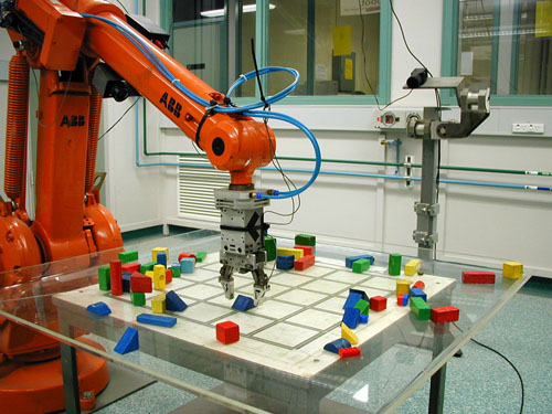
But that philosophy doesn't really apply to Mimic Arm. We don't care where the hand is, as long as its appearance roughly mimicking what your real arm is doing. And the user is controlling it in real time, so if they need to adjust the position, they can do it very easily and intuitively. This may seem like a small change, but it dramatically changes how the arm is approached.
For one thing, we treat Degrees Of Freedom (DOF) a lot differently. Degrees Of Freedom just refers to how many joints your robot arm has, ie, how many ways it can transform its own motion. For a robot arm that only cares where it puts its own hand, it's usually more efficient for these to not be the same joints as a human arm, since what works for us usually isn't quite the same as what's needed for the job the robot needs to do. Maybe it doesn't need as many, or needs more, or maybe it needs wider or narrower flexibility to fit the application. In any case, you typically end up with something like this, which does that one robot thing really well but isn't exactly very human.
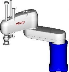
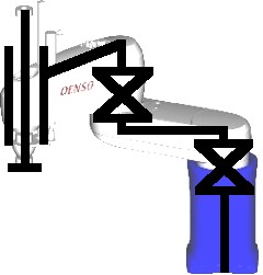
If the you want to know more about what the diagrams mean (they're called the Denavit-Hartenberg Convention for kinematic drawings), check out this link for a full explanation. Short version, the hourglass looking joints rotate into the page, and the circle ones are rotating across it.
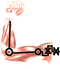
This one isn't quite perfect either, since it clusters a lot of motors up at the shoulder, and it requires a lot of the DOFs drawn out to move in concert to perform some common motions. Even if you spread them out a bit (arm 1 below), the mathematics for this arm are very complex. So we came up with our own model (arm 2 below), which does things a bit more easily by moving one motor to become the bicep. It can still reach every position a human arm can, but needs fewer motors at a time for common movements, and is generally easier to handle.

The mathematics we used would also change from this decision. For regular robot arms, you typically have a destination for the hand which is then met by the motors of the arm. The mathematical operations needed to figure out how to get it there are referred to as Inverse Kinematics, or finding the appropriate arm angles needed to hit a point (or series of points) in three dimensions. Mimic Arm is given points by the Kinect and then must find the proper angles so that it looks like it's moving naturally, and thus uses Forward Kinematics. This actually made our job a little easier, since forward kinematics tend to be easier than inverse, but I'll get back to that in the implementation post.
2) Camera Based Tracking

It's worth noting that we did not originally start with the Kinect, instead opting for a linux-based camera, the Asus Xtion Pro. Our hope was to make the system entirely self contained, without needing a laptop as an intermediary, which could be done with compact linux systems like the BeagleBone Black but not with a Windows operating system. However, we later found out that the entire non-windows software community for motion tracking has been destroyed by an acquisition of the PrimeSense skeletal tracking library by Apple, meaning that the only viable platform for camera tracking is now the Kinect, with the Microsoft SDK, on a windows machine. Not a great scenario, so stay away unless you want to accidentally spend hundreds of dollars on defunct hardware like we did.
Despite not having linux support, the new Kinect camera really is a brilliant machine, doing some significant under-the-hood processing to bring you a fully mapped skeletal model of the human body in real time. The speed and accuracy of the platform meant that we had very little to do on the tracking end other than fetch the numbers that the Kinect's SDK throws at you, though we did end up smoothing out a little bit of residual noise to make the arm's movements less jumpy.
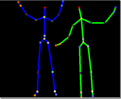
Things the Kinect can't do, though, are tell when your arm is out of sight, and track what your hand is doing. These weren't big issues for us, since we couldn't afford to build an arm powerful enough to support a fully articulated robotic hand (discussed in the next section), and since we weren't expecting users to be twirling around as they moved the arm. They're problems that could be approached by engineers in the future, possibly by using inertial tracking rather than just a camera, but that's a job for another time.
3) Superior Power and Speed
One of the biggest problems that we could identify with a lot of the hobby-type mimic arms that already existed was that the motors they were using were simply too lightweight to perform motions properly. Motors like these offer only a pitiful 50 ounce inches of torque at the max, and can only be controlled through PWM (pulse width modulation), which means they give back no information on whether they've maxed out their torque limit, destroyed their own gearing, or even just where they are physically in terms of angular position.
Making the arm move powerfully and smoothly was one of our biggest concerns from the start, so this needed to be solved in the design phase. Running the kinematic calculations, we were going to want a much higher torque than oz/in at the shoulder to support an arm of 12 inches or more. We had already sacrificed a complex end effector out of concerns for cost - motors powerful enough to lift an arm with the weight of a motorized hand on the end would almost certainly be out of our price range. But making the arm out of cheap materials and at miniaturized size was out of the question. We wanted to see it move, and we wanted users to be able to relate to that movement; that meant a balance between price and more power.
In addition, we wanted more flexibility in terms of what the arm could return to the computer; things like current position, temperature, and load torque, as well as options for emergency shutoff in case the arm got blocked or overheated. Putting all our money and time into an arm that would simply break as soon as it got stressed was the last thing anyone wanted, and we were willing to put up a little more funding upfront to prevent that.
With these conditions in mind, we ended up going with the Dynamixel servo line:


The Dynamixel AX-12s were the perfect mix of power and flexibility we were looking for, with over 200 oz/in of torque and a full onboard microcontroller with settings and feedback for position, speed, motor rotation limits, max torque, and a host of alarm settings that could shut the system off in a pinch. The weren't bad on price either, coming in at just $45 for an order of magnitude more functionality than the simple PWM servos we'd seen before. For the shoulder, though, we wanted even more power, and decided to go with the upgraded MX-64: a $300, 1000 oz/in beast of a servo that would be more than enough to lift our arm by almost twice our safety margin.
The real tradeoff for these motors was in their complexity. PWM may be limited, but it is also simple, and can be implemented on any Arduino microcontroller. These guys, on the other hand, well... they need some extra work. A whole semester's worth of work, as it turned out.
But all that shall be left for another time. Part 2 of this series will address implementation of the system, from technology to coding to completion.
See you then!
- Lucian


